Cable tray catalog parts
In the Project Environment dialog, define the following to create a new Catalog Part for a cable tray.
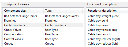
Component class and functional codes
In the project database, the configuration object Component classes must have a component class of type "Cable Tray Parts". This component class is linked to cable tray related Functional codes that define what kind of logical functions cable tray parts can have in the 3D model.
GDL for cable tray part
Create a GDL component for the cable tray part.
Normally, we recommend creating the GDL for a new cable tray part by copying and modifying an existing GDL. However, in this example, we manually create the GDL for a channel-type component.
Do the following:
-
In the CADMATIC desktop, select Object > Library and Project Database.
-
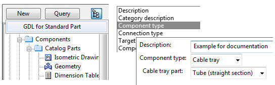
In the Project Environment dialog, browse to [library or project] > Components > Catalog Parts > Geometry and select New > GDL for Standard Part.
-
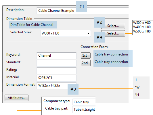
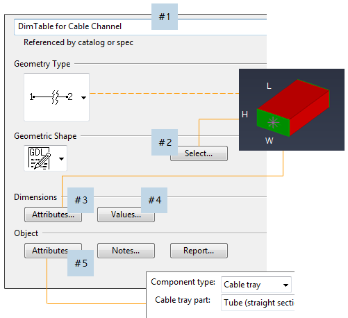
In the Edit Attributes dialog, select the required attributes.
In this example, we select the attributes Description and Component type, setting the type to "Cable tray". This action also adds the Cable tray part attribute, which we set to "Tube (straight section)".
Note: Penetrations for cable ways are created as equipment.
-
In the Select geometry type dialog, select DM_GT_PIPE(1) and clear the option Use templates.
-
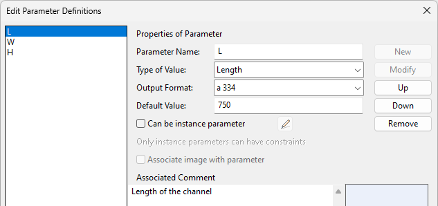
In the Component Modeller application, define the parameters of the GDL component.
-
The Width and Height parameters must be defined to parameterize the profile of the channel. They are also used for setting the properties of the end nodes.
-
The Length parameter must be defined to parameterize the distance between the nodes at the ends of the cable tray. Otherwise, length cannot be controlled via the Dimension Table.
Important: Width must be greater than Height.
-
-
Create the GDL component using the following rules:
-
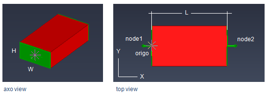
Local x-axis is the length axis.
Local y-axis is the width axis.
-
First node is at the origin (start of the channel), second node (end of the channel) is relative to the first node in x-axis direction.
-
First node point is at {0,0,0}.
-
Second node point is at {Length, 0, 0}.
-
-
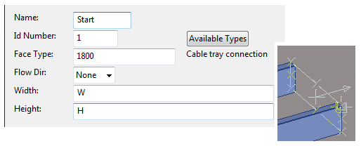
Face Type of end nodes is "Cable tray connection".
-
Width and Height of end nodes refer to the width and height parameters of the GDL. These parameters are used as key dimensions in specifications, and as reference points in routing.
In the picture below, node's width is set to the GDL parameter "W", and node's height is set to the GDL parameter "H".
-
Direction of width in the node is set so that the cross product of the length axis and the width axis yields the z-axis (points up).
Note: Cable tray parts have a minimum length of 100 mm. If the "MinLength" dimension exists in the Dimension Table, then its value (if > 10 mm) is used instead.
-
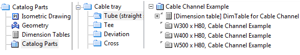
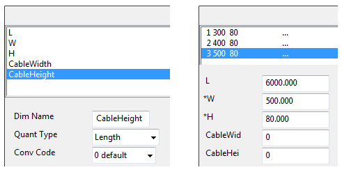
Dimension table for cable tray part
Create a Dimension Table for the cable tray part.
Selecting the GDL component adds its parameters to the Dimension Table as attributes, allowing you to parameterize their values.
You can also add additional attributes. To enable fill rate calculation, the Dimension Table must have appropriate values for the parameters that define the real maximum area that can be filled with cables to achieve 100% fill rate:
- CableWidth
- CableHeight
Important: CableWidth must be greater than CableHeight.
Additionally, it is possible to define the distance from the centerline of the cable tray to the bottom of the cable section. This allows the position of the cable section to be corrected if it is located too high or too low in the fill rate view. Use the following Dimension Table parameter to place the bottom of the cable section above (positive value) or below (negative value) the centerline of the cable tray:
-
CableBottom
Note: For cable tray parts, the L (length) dimension is not mandatory. If length does not exist, the stock length is measured from the GDL (between nodes) while routing.
Note: If Elotools is installed, the values in the Dimension Table can be set using the CADMATIC desktop command Object > Tools > Run DM Tools > Dimension table Excel tool.
Catalog part for cable tray part
Create the Catalog Part for the cable tray.